-
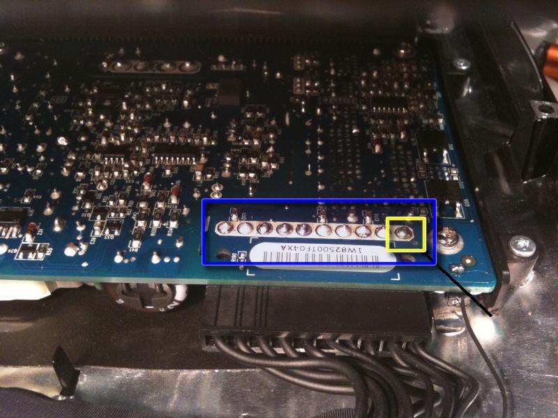
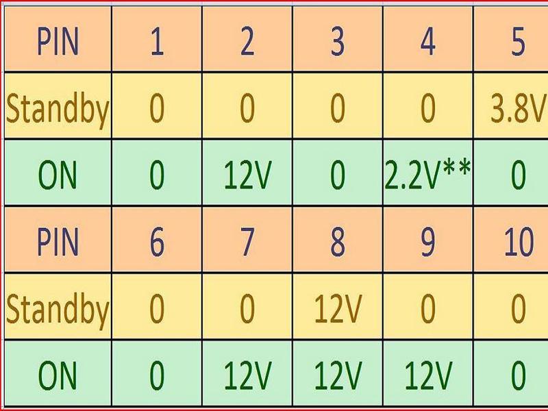
Use the chart provided as a reference and test the various voltages with your meter being sure to restrict the probes to the 10 solder joints on the PSU connector shown within the BLUE rectangle. Shorting any part of the PCB will almost certainly cause damage to the imac
-
-
All voltage measurements are taken with PIN 1 as reference (Marked with the YELLOW square). Pin 1 is marked on the board by a dot and is the right hand pin when viewed as shown in photos

-
-
STANDBY means system connected to mains outlet but imac turned off – Diagnostic LED 1 will be illuminated on logic board
-
-
Pin 5 is the PSU enable line – Logic board pulls this line low (0V) to enable PSU (probably via a resistor)
-
-
Pin 4 voltage varies according to the PSU temperature and is inversely proportional to PSU temperature. Higher Temp = Lower Voltage. My measurement was taken at around **24 Deg Celsius.
-
-
Reassemble your iMac in reverse order. When lowering the LCD ensure you don’t crimp or crush the LCD back-light cables
